


| Categories | Lift Table Manuals, OTC Lift Table Manuals, Robinair Lift Table Manuals, SPX Lift Table Manuals |
|---|---|
| Tags | OTC 1822, SPX 1822 |
| Download File |
|
| Document File Type | |
| Copyright | Attribution Non-commercial |
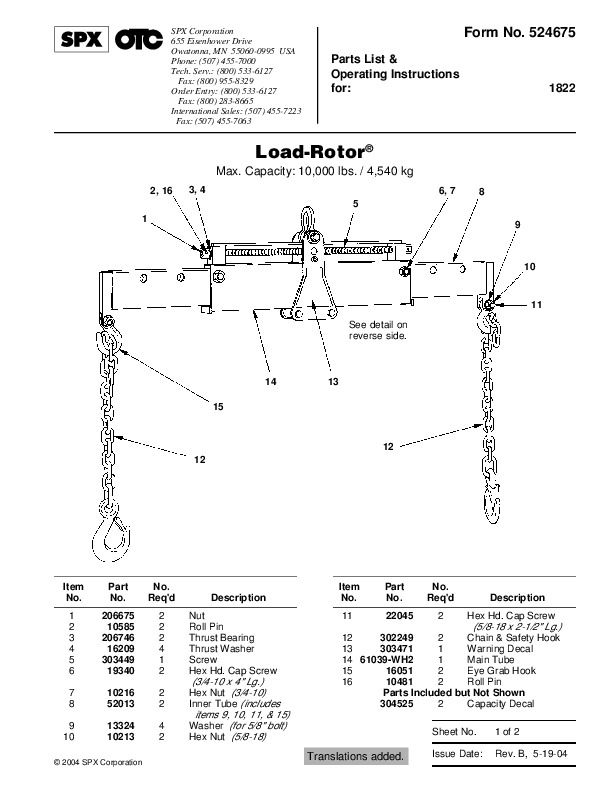
Form No. 524675 Parts List & Operating Instructions for: 1822 Load-Rotor® Max. Capacity: 10,000 lbs. / 4,540 kg 2, 16 1 3, 4 5 9 6, 7 8 10 11 See detail on reverse side. 14 15 13 12 12 Item No. Part No. 206675 10585 206746 16209 303449 19340 10216 52013 13324 10213 No. Req’d 2 2 2 4 1 2 2 2 4 2 Description Nut Roll Pin Thrust Bearing Thrust Washer Screw Hex Hd. Cap Screw Item No. 11 Part No. 22045 No.
Req’d 2 Description Hex Hd. Cap Screw (5/8-18 x 2-1/2 ” Lg.) 12 302249 2 Chain & Safety Hook 13 303471 1 Warning Decal 14 61039-WH2 1 Main Tube 15 16051 2 Eye Grab Hook 16 10481 2 Roll Pin Parts Included but Not Shown 304525 2 Capacity Decal Sheet No. 1 of 2 Rev. B, 5-19-04 (3/4-10 x 4 ” Lg.) Hex Nut (3/4-10) Inner Tube (includes items 9, 10, 11, & 15) Washer (for 5/8 ” bolt) Hex Nut (5/8-18) 2004 SPX Corporation Translations added. Issue Date: Parts List & Operating Instructions Form No. 524675, Sheet 1 of 2, Back 18 2 1 Refer to any operating instructions included with the product for detailed information about operation, testing, disassembly, reassembly, and preventive maintenance. Items found in this parts list have been carefully tested and selected by OTC. Therefore: Use only OTC replacement parts! Additional questions can be directed to the OTC Technical Services Department. 3 17 4 5 16 Maintenance 1. Regularly clean and lubricate the tilt adjustment screw. See Figure 1. 2. Keep the four load bearing bolts fastened securely. See Figure 1. 6 15 7 8 14 13 9 Torque to 25 – 30 ft. lbs. 12 10 11 .000 .020 (4 places) Note: Grease bearings (Item 10) before assembly. Item No. 1 2 3 4 5 6 7 8 9 Part No. 208112 208149 12004 10075 207255 208110 524674 303452 12726 No. Req’d Description Needle Bearing Spacer Inner Bearing Race Hex Hd. Cap Screw (1/2-13 x 3/4 ” Lg.) Hex Nut (1/2-13) Spacer Trade Name Decal Roller Locknut (5/8-18; torque (5/8-18 x 4-1/2 ” Lg.) Wear Pad Side Plate Hex Hd. Cap Screw (1/2-13x 4-1/2 ” Lg.) Screw Block Pin to 25-30 ft. lbs.) Parts List & Operating Instructions Safety Precautions Form No. 524675 · · Caution: To prevent personal injury, Wear eye protection that meets the requirements of ANSI Z87.1 and OSHA. Read, understand, and follow all instructions and safety precautions included with the Load Rotor®. If the operator cannot read English, operating instructions and safety precautions must be read and discussed in the operator’s native language. Si el operador no puede leer inglés, las instrucciones de operación y las precauciones de seguridad deberán leerse y comentarse en el idioma nativo del operador. Si l’utilisateur ne peut lire l’anglais, les instructions et les consignes de sécurité doivent lui être expliquées dans sa langue maternelle. Secure all adjusting bolts before lifting a load. Attach BOTH lift arms to the load being lifted; do NOT use a single arm setup. Do not attempt to lift a load that exceeds the maximum capacity of 10,000 lbs. / 4,540 kg. Overloaded equipment can fail and cause personal injury. To ensure the load bearing chains are not stressed beyond their capacities, do not adjust the load rotor to an angle greater than 30° (see Figure 2), and do not spread the load bearing chains more than a total of 90° for both chains (see Figure 3). The load rotor is not designed for overhead lifting applications. Stay out from underneath a load being lifted or suspended. · Operating Instructions The Load Rotor is designed to handle and position large, bulky components. The horizontal tilt can be adjusted to compensate for off-center loads, or adjusted to a certain angle for a component being positioned. 1. Hook the load rotor to a crane or hoist. 2. Attach the two load bearing chains to the component. Adjust the extension arms in or out to keep the chain angle at a minimum. 3. Verify the bolts holding the extension arms are securely fastened. See Figure 1. Caution: To maintain stability and ensure the load bearing chains are not stressed beyond their capacities, Load Bearing Bolts Tilt Adjustment Screw Extension Arm Adjusting Bolts · Do not adjust the load rotor to an angle greater than 30°. See Figure 2. Figure 1 · Do not spread the load bearing chains more 4. Lift the component enough to locate the center of balance. Level or adjust the angle of the load rotor by using a wrench to turn either end of the threaded adjustment screw. than a total of 90° for both chains. See Figure 3. 30° Max. (both sides) 45° Max. 45° Max. 45° Max. 45° Max. Figure 3 Sheet No. 2 of 2 Rev. B, 5-19-04 Figure 2 2004 SPX Corporation Issue Date: