| Categories | Power Tool |
|---|---|
| Download File |
|
| Document File Type | |
| Copyright | Attribution Non-commercial |
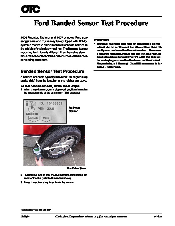
Ford Banded Sensor Test Procedure 2006 Freestar, Explorer and 2007 or newer Ford passenger cars and trucks may be equipped with TPMS systems that have wheel mounted sensors banded to the middle of the inside wheel rim. The Banded Sensor mounting technique is different than the valve stem mounted sensor technique and requires a different sensor testing procedure. Important: · Banded sensors can slip on the inside of the wheel rim to a different location other than directly across from the tire valve stem.
Power Tool User Manual Free Download. HAVC Operator’s Manual. Auto AC Lift Power Free Instruction Manual Download PDF.
If sensor does not activate, move the tool 45 degrees in each direction around the tire with the tool antenna laying across the tire tread as illustrated. Repeat steps 1 through 3 until the sensor is located / activated. Banded Sensor Test Procedure A banded sensor is typically mounted 180 degrees (opposite side) from the location of the rubber tire valve. To test banded sensors, follow these steps: 1 When the activate screen is displayed, position the tool on the opposite side of the valve stem (180 degrees). Activate Screen Tire Valve Stem 2 Position the tool so that the tool antenna lays across the tread of the tire (refer to illustration above). 3 Press the activate key to activate the sensor. Technical Service: 800-533-6127 12/19/07 2007, SPX Corporation · Printed in U.S.A · 547370 …