


| Categories | Lift Table Manuals, OTC Lift Table Manuals, Robinair Lift Table Manuals, SPX Lift Table Manuals |
|---|---|
| Tags | OTC 00942, OTC 014, OTC 1728, SPX 00942, SPX 014, SPX 1728 |
| Download File |
|
| Document File Type | |
| Copyright | Attribution Non-commercial |
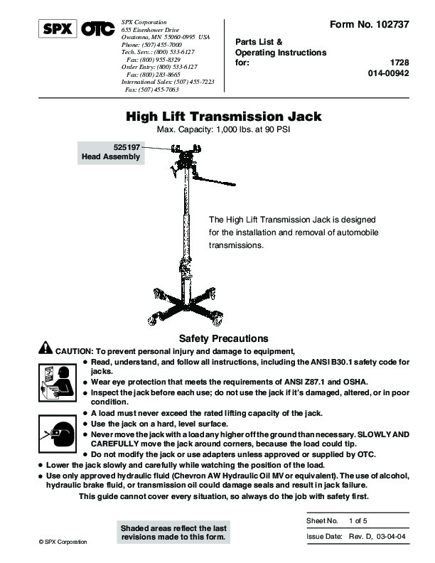
Form No. 102737 Parts List & Operating Instructions for: 1728 014-00942 High Lift Transmission Jack Max. Capacity: 1,000 lbs. at 90 PSI 525197 Head Assembly The High Lift Transmission Jack is designed for the installation and removal of automobile transmissions. Safety Precautions CAUTION: To prevent personal injury and damage to equipment, · Read, understand, and follow all instructions, including the ANSI B30.1 safety code for jacks.
· Wear eye protection that meets the requirements of ANSI Z87.1 and OSHA. · Inspect the jack before each use; do not use the jack if it’s damaged, altered, or in poor condition. · A load must never exceed the rated lifting capacity of the jack. · Use the jack on a hard, level surface. · Never move the jack with a load any higher off the ground than necessary. SLOWLY AND CAREFULLY move the jack around corners, because the load could tip. · Do not modify the jack or use adapters unless approved or supplied by OTC. Lower the jack slowly and carefully while watching the position of the load. Use only approved hydraulic fluid (Chevron AW Hydraulic Oil MV or equivalent). The use of alcohol, hydraulic brake fluid, or transmission oil could damage seals and result in jack failure. This guide cannot cover every situation, so always do the job with safety first. Sheet No. SPX Corporation · · 1 of 5 Shaded areas reflect the last revisions made to this form. Issue Date: Rev. D, 03-04-04 Parts List & Operating Instructions Form No. 102737, Sheet 1 of 5, Back Operating Instructions This is a two-stage transmission jack. The air stage is designed to quickly move the adapter into position, and is completed with an automatic lock function that prevents loss of load. The following hydraulic stage is designed to align the adapter with the transmission. 1. Lift the vehicle on a hoist. 2. Position the jack under the transmission. 3. Connect the air supply to the jack. (90 psi of clean, dry air is required for the capacity of this jack.) 4. Press the pedal marked UP to raise the adapter until the cylinder locks into place (at about 20 inches). The air hose can be removed at this time. CAUTION: If a load is transferred to the adapter when the air cylinder is only partially raised, the cylinder will drop suddenly. To eliminate this problem, always raise the cylinder to the point where the mechanical lock engages. 5. Check the placement of the jack. The transmission’s center of weight, or balance point, should be centered over the jack adapter, with the power output end located over the adapter bracket between the chains. The jack’s mechanical lock must be engaged. 6. Close the hydraulic release valve by turning the knob clockwise (CW). 7. Pump the jack handle to finish raising the adapter to the transmission. Use the controls on the adapter to roll or tip the adapter as needed to align it with the transmission. 8. Push in the four adapter brackets until they touch the transmission. Use the chains to secure the transmission to the adapter. 9. Support the engine, and remove the transmission according to instructions in the vehicle service manual. 10. Slowly turn the hydraulic release valve counterclockwise to lower the hydraulic stage. Lower the air stage by pressing the DOWN foot pedal. If the load is already resting on the mechanical lock, attach the air hose, and press the UP pedal briefly so the mechanical lock will release. The air stage should then lower when the DOWN pedal is pressed. Bleeding Air from the Hydraulic System Air can accumulate within a hydraulic system during shipment or after prolonged use. This entrapped air causes the jack to respond slowly or feel “spongy. ” To remove the air: 1. Tilt the jack onto two casters with the pump handle positioned below the cylinder. 2. Open the release valve by turning the knob counterclockwise (CCW). 3. Pump the handle until resistance is felt. 4. Close the release valve by turning the knob all the way clockwise (CW). 5. Continue pumping the handle while returning the jack to its upright position. Parts List & Operating Instructions Jack Assembly 1 2 3 Form No.