| Categories | Lift Table Manuals, OTC Lift Table Manuals, Power Tool, Robinair Lift Table Manuals, SPX Lift Table Manuals |
|---|---|
| Tags | OTC 7704, SPX 7704 |
| Download File |
|
| Document File Type | |
| Copyright | Attribution Non-commercial |
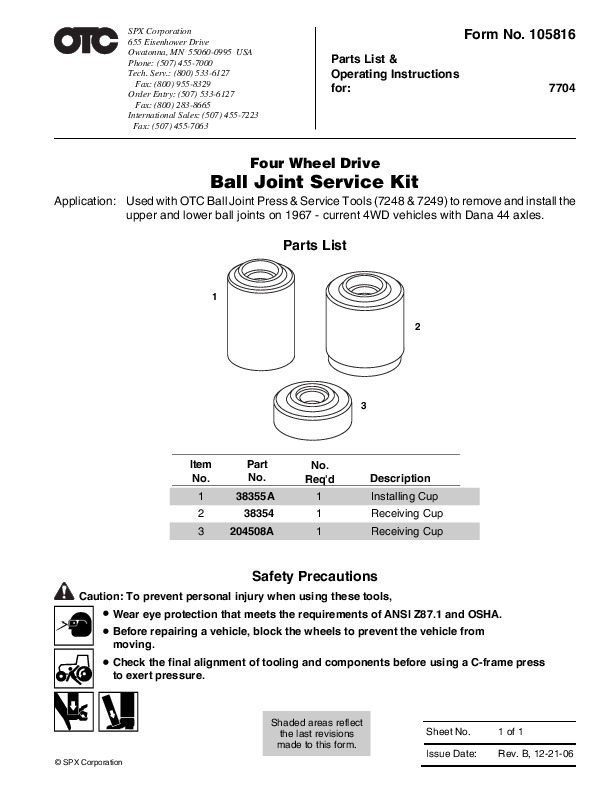
SPX Form No. 105816 Parts List & Operating Instructions for: 7704 Four Wheel Drive Ball Joint Service Kit Application: Used with OTC Ball Joint Press & Service Tools (7248 & 7249) to remove and install the upper and lower ball joints on 1967 – current 4WD vehicles with Dana 44 axles.
Power Tool User Manual Free Download. HAVC Operator’s Manual. Auto AC Lift Power Free Instruction Manual Download PDF.
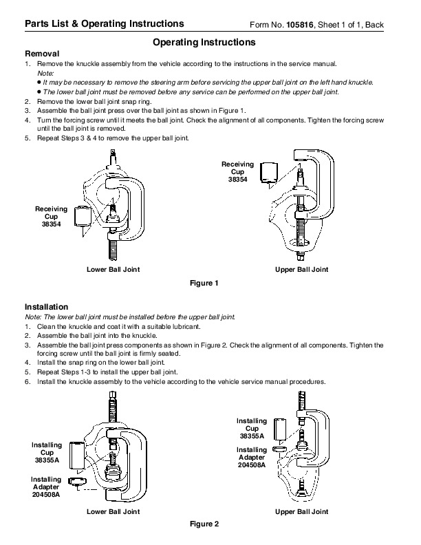
Parts List 1 2 3 Item No. 1 2 3 Part No. 38355A 38354 204508A No. Req’d Description Installing Cup Receiving Cup Receiving Cup Safety Precautions Caution: To prevent personal injury when using these tools, · Wear eye protection that meets the requirements of ANSI Z87.1 and OSHA. · Before repairing a vehicle, block the wheels to prevent the vehicle from moving. · Check the final alignment of tooling and components before using a C-frame press to exert pressure. Shaded areas reflect the last revisions made to this form. SPX Corporation Sheet No. Issue Date: 1 of 1 Rev. B, 12-21-06 Parts List & Operating Instructions Removal Form No. 105816, Sheet 1 of 1, Back Operating Instructions 1. Remove the knuckle assembly from the vehicle according to the instructions in the service manual. Note: It may be necessary to remove the steering arm before servicing the upper ball joint on the left hand knuckle. The lower ball joint must be removed before any service can be performed on the upper ball joint. 2. Remove the lower ball joint snap ring. 3. Assemble the ball joint press over the ball joint as shown in Figure 1. 4. Turn the forcing screw until it meets the ball joint. Check the alignment of all components. Tighten the forcing screw until the ball joint is removed. 5. Repeat Steps 3 & 4 to remove the upper ball joint. · · Receiving Cup 38354 Receiving Cup 38354 Lower Ball Joint Upper Ball Joint Figure 1 Installation Note: The lower ball joint must be installed before the upper ball joint. 1. Clean the knuckle and coat it with a suitable lubricant. 2. Assemble the ball joint into the knuckle. 3. Assemble the ball joint press components as shown in Figure 2. Check the alignment of all components. Tighten the forcing screw until the ball joint is firmly seated. 4. Install the snap ring on the lower ball joint. 5. Repeat Steps 1-3 to install the upper ball joint. 6. Install the knuckle assembly to the vehicle according to the vehicle service manual procedures. Installing Cup 38355A Installing Cup 38355A Installing Adapter 204508A Lower Ball Joint Upper Ball Joint Installing Adapter 204508A Figure 2 …