| Categories | Lift Table Manuals, OTC Lift Table Manuals, Power Tool, Robinair Lift Table Manuals, SPX Lift Table Manuals |
|---|---|
| Tags | OTC 927, SPX 927 |
| Download File |
|
| Document File Type | |
| Copyright | Attribution Non-commercial |
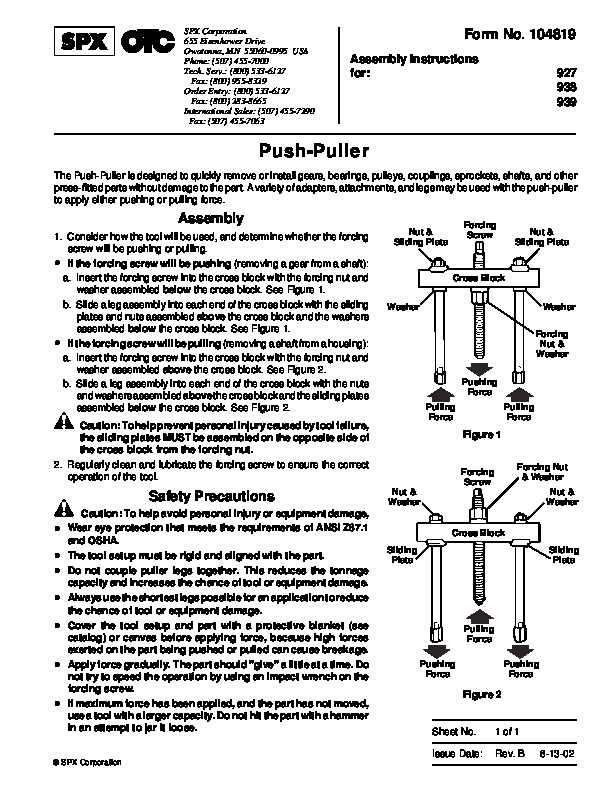
SPX Form No. 104819 Assembly Instructions for: 927 938 939 Push-Puller The Push-Puller is designed to quickly remove or install gears, bearings, pulleys, couplings, sprockets, shafts, and other press-fitted parts without damage to the part.
Power Tool User Manual Free Download. HAVC Operator’s Manual. Auto AC Lift Power Free Instruction Manual Download PDF.
A variety of adapters, attachments, and legs may be used with the push-puller to apply either pushing or pulling force. Assembly 1. Consider how the tool will be used, and determine whether the forcing screw will be pushing or pulling. If the forcing screw will be pushing (removing a gear from a shaft): a. Insert the forcing screw into the cross block with the forcing nut and washer assembled below the cross block. See Figure 1. b. Slide a leg assembly into each end of the cross block with the sliding plates and nuts assembled above the cross block and the washers assembled below the cross block. See Figure 1. If the forcing screw will be pulling (removing a shaft from a housing): a. Insert the forcing screw into the cross block with the forcing nut and washer assembled above the cross block. See Figure 2. b. Slide a leg assembly into each end of the cross block with the nuts and washers assembled above the cross block and the sliding plates assembled below the cross block. See Figure 2. Nut & Sliding Plate Forcing Screw Nut & Sliding Plate · Cross Block Washer Washer Forcing Nut & Washer Pushing Force Pulling Force Pulling Force · Caution: To help prevent personal injury caused by tool failure, the sliding plates MUST be assembled on the opposite side of the cross block from the forcing nut. 2. Regularly clean and lubricate the forcing screw to ensure the correct operation of the tool. Figure 1 Forcing Nut & Washer Nut & Washer Cross Block Sliding Plate Sliding Plate Forcing Screw Nut & Washer Safety Precautions · Caution: To help avoid personal injury or equipment damage, Wear eye protection that meets the requirements of ANSI Z87.1 and OSHA. The tool setup must be rigid and aligned with the part. Do not couple puller legs together. This reduces the tonnage capacity and increases the chance of tool or equipment damage. Always use the shortest legs possible for an application to reduce the chance of tool or equipment damage. Cover the tool setup and part with a protective blanket (see catalog) or canvas before applying force, because high forces exerted on the part being pushed or pulled can cause breakage. Apply force gradually. The part should “give ” a little at a time. Do not try to speed the operation by using an impact wrench on the forcing screw. If maximum force has been applied, and the part has not moved, use a tool with a larger capacity. Do not hit the part with a hammer in an attempt to jar it loose. Pulling Force Pushing Force Pushing Force Figure 2 Sheet No. Issue Date: 1 of 1 Rev. B 8-13-02 SPX Corporation …