
| Categories | Power Tool |
|---|---|
| Tags | Robinair 6585 |
| Download File |
|
| Document File Type | |
| Copyright | Attribution Non-commercial |
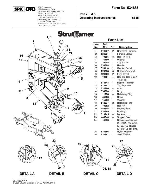
SPX Corporation 655 Eisenhower Drive Owatonna, MN 55060-0995 USA Phone: (507) 455-7000 Tech. Serv.: (800) 533-6127 Fax: (800) 955-8329 Order Entry: (800) 533-6127 Fax: (800) 283-8665 International Sales: (507) 455-7223 Fax: (507) 455-7063 Form No. 534685 Parts List & Operating Instructions for: 6585 4, 5 7 6 18 21 25 17 TM Parts List Item No. Part No. 519937 534691 10585 16450 10005 534688 520110 223268 520109 10101 518443 518451 533880 534690 11998 46963 15953 512037 10982 440645 534689 519945 440644 6583 Qty.
Heating, Ventilating and Air Conditioning User Manual Free Download. HAVC Operator’s Manual. Auto AC Free Instruction Manual Download PDF.
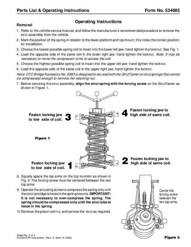
Description Universal Trunnion Forcing Screw Roll Pin (1 “) Washer Cap Screw Handle Caution Decal Rubber Grommet Logo Decal Hex Hd. Cap Screw (5/811) Bottom Trunnion Top Trunnion Arm Body Retaining Ring Decal Washer Retaining Ring Roll Pin Locking Foot Bushing Locknut Support Foot Bridge consists of (4) 14528 hair pins; (2) 507739 straps; (2) 519708 adj. pins. Nylon Washer Stop Washer 534686 534687 DETAIL A DETAIL B DETAIL C DETAIL D Sheet No. 1 of 2 2006 SPX Corporation (Rev. A, April 10, 2006) Parts List & Operating Instructions Form No. 534685, Sheet 1 of 2, Back Safety Precautions Warning: Spring compression creates a potentially dangerous situation because of the energy stored between the spring mounts. To prevent personal injury, · Read, understand, and follow the safety precautions and operating instructions included with the StrutTamer. If the operator cannot read these instructions, operating instructions and safety precautions must be read and discussed in the operator’s native language. Wear eye protection that meets ANSI Z87.1 and OSHA standards. Use this equipment for automotive strut springs only. Check the condition of the StrutTamer before each use; do not use the equipment if it is in poor condition. Position upper hooks as far from lower hooks as possible. Hand tighten locking rings around the hooks before compressing the spring. Compress the spring only until it is loose in its spring mounts. Stop compressing if the spring or the arms bottom out. DO NOT EXCEED 50 FT. LBS. OF TORQUE ON THE ACTUATING SCREW. Do not remove the piston rod nut until the spring is compressed enough to be loose in the mount. Assembly The StrutTamer may be mounted on a wall, or on the optional mobile stand (part no. 6582). Use the top two holes in the StrutTamer body to mount the StrutTamer on No. 6582 optional stand as shown. (Hardware is included with the stand.) Use all four holes on the back of the StrutTamer body to mount the StrutTamer to a wall. Parts List & Operating Instructions Removal Form No. 534685 Operating Instructions 1. Refer to the vehicle service manual, and follow the manufacturer’s recommended procedure to remove the strut assembly from the vehicle. 2. Mark the position of the spring in relation to the lower platform and top mount; this notes the correct position for installation. 3. Choose the lowest possible spring coil to insert into the lower left jaw; hand tighten the locknut. See Fig. 1. 4. Load the opposite side of the same coil in the lower right jaw; hand tighten the locknut. Note: It may be necessary to move the compressor arms to access the coil. 5. Choose the highest possible spring coil to insert into the upper left jaw; hand tighten the locknut. 6. Load the opposite side of the same coil in the upper right jaw; hand tighten the locknut. Note: OTC Bridge Accessory No. 6583 is designed to be used with the StrutTamer on strut springs that cannot be compressed enough to remove the retaining nut. 7. Before servicing the strut assembly, align the strut spring with the forcing screw on the StrutTamer as shown in Figure 1. Fasten locking jaw to low side of coil. 3 4 Fasten locking jaw to high side of same coil. Figure 1 Fasten locking jaw to low side of coil.